 Radome Capabilities
- Advantages of Radome Protection
- Basic Construction Techniques
- Design Enhancements to Maximize Performance
- Random Panel Geometry Eliminates Coherent Reflections
- Tuning a Space Frame Radome
- Frequency Matching a Sandwich Radome
- Eliminating Water Accumulation
- Selecting a Radome to Match Your Requirements
- Operating Frequency Considerations
- Initial Cost Approximation
- Mechanical Considerations
- Complete Radome System Capability
- Installation Services Throughout the World
- Support Equipment for Full Operational Status
- Advantages of Selecting AFC as Your Radome Source
- Experience of Over 30 Years
- Capabilities to Match Your Fast Response Requirements
- Quality to Last
- Related Standard and Specialized Products
- Standard and Customized Antennas
- Turnkey Shelters for Specialized Applications
- Custom Waveguide Components and Low Loss Transmission Lines
Advantages of Radome Protection
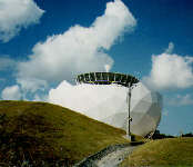
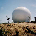
Radar domes, or Radomes, are used to enclose antennas. Typical applications include antennas for radar, telemetry, tracking, communications, surveillance, and radio astronomy. The first radome was constructed 40 years ago; they are currently in use throughout the world, from the tropics to the arctic.The principal purpose of a radome is to shield the antenna from the environment. This improves system availability since the antenna is not affected by winds, rain, or ice. It can also improve performance since high winds can distort the shape and pointing direction of the reflector.
Radomes also provide a benign environment for any electronics, and personnel, that must be located near the antenna. This is especially significant in harsh weather such as temperature extremes, blowing sand or dirt, salt spray, and freezing rain.
Radomes have proven to be very effective when considering life cycle costs. Since the antenna is in a protected environment, maintenance costs are held to a minimum. The structural requirements of the antenna are less stringent, resulting in reduced fabrication and installation costs plus the use of smaller positioning motors.
The final advantages of a radome are that a dome structure is aesthetically pleasing. Radomes are also very effective in concealing the type of equipment inside the dome.
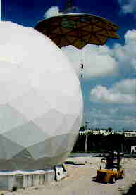
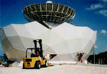
Basic Construction Techniques
Rigid radomes are designed using the principles of a geodesic dome. This technique uses straight or circular arc structural elements in tension, arranged in a framework of geometric patterns such as triangles and hexagons. This design results in a structure that provides maximum volume with minimum material, reduces stress and weight, and may be tailored to meet exacting electromagnetic scattering requirements.
 |
 |
 |
AFC currently offers four different types of rigid radomes: the thin membrane wall dielectric space frame (DSF), the solid laminate DSF radome and the two amd three layer composite sandwich foam core DSF radome. Each type provides unique operating characteristics and benefits. Although all types may be used in a variety of different applications, the sandwich foam core approach accommodates a temperature compensated environment for electronics or personnel. Radome size varies from several inches to 150 ft. in diameter. For more details, see advantages of dielectric radome technology.
Design Enhancements to Maximize Performance
The ideal radome would appear totally transparent to any electromagnetic signal. Since this is not possible, radomes must be designed to minimize the impact of the radome on the enclosed antenna. Application requirements determine the importance of signal distortions such as insertion loss, boresight error, and scattering into the antenna sidelobes. AFC employs several different techniques to improve performance goals.Random Panel Geometry Eliminates Coherent Reflections
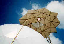
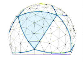 The geometry of a particular radome panel may cause a scattering error at a certain frequency. If the radome were constructed of identical panels, the error would be repeated. To eliminate this problem, some AFC radomes utilize a pseudo-random panel design.
Random panel design is achieved by starting with one of the Platonic Forms; which is a method of dividing a sphere into 4, 6, 8, 12, or 20 identical subdivisions. One of the subdivisions is then further divided into panels of different shapes. By repeating this pattern, a complete sphere can be constructed that will provide the pseudo-random panel distribution without extensive fabrication costs.
Tuning a Space Frame Radome
|
The thin wall dielectric space frame, solid laminate and sandwich foam core DSF radomes are assembled from multiple panels. At the panel edges, the dielectric is reinforced to support structural loads and mechanical fasteners. Assembled, the panel edge frameworks act as capacitive loaded dielectric strut antenna elements, scattering signals according to radome panel geometry, strut thickness and the enclosed antenna pattern. Scattering loss is often 4 to 10 times larger than the ordinary wall insertion loss. To compensate, AFC impedance matches, "tunes", the radome by glassing wire arrays into the strut seam joint surface. The inductive wires cancel the capacitance of the dielectric struts. To even further help reduce the influence of strut scatterers, panel geometry and radome symmetry are chosen to minimize boresight shift and sidelobe perturbations. |
Frequency Matching a Sandwich Radome
The foam sandwich radome panels consist of a foam core sandwiched between two thin sheets of fiberglass. This technique provides excellent thermal insulation and minimal transmission losses at selected frequencies. The insertion loss of sandwich material is a function of the thickness of the core. By varying the thickness, optimal performance is achieved for the particular frequency of interest. This is known as quarterwave matching.Eliminating Water Accumulation
| Additive Rain Transmission Loss | Additive Rain Noise Temperature |
 |
 |
With any standard radome, water will tend to collect on the exterior surface and run off in sheets; significantly affecting performance. AFC utilizes a proprietary technique to provide a long lasting hydrophobic surface. This causes the radome to remain dryer, water to bead and run off in rivulets instead of sheeting. A hydrophobic surface significantly reduces ice adhesion.
Selecting a Radome to Match Your Requirements
In most applications the two primary factors in selecting the type of radome are performance and cost. Additional considerations may include ease of transportation, installation, snow loading and wind/gust rating. All applicable factors must be considered in order to insure an optimum match.Operating Frequency Considerations
In general, thin wall dielectric space frame radomes are considered broad band structures suitable for operation over a relatively wide range of frequencies. Foam core sandwich radomes are more frequency specific since the thickness of the core is varied to achieve the desired insertion loss for a particular frequency band. In order to maintain minimum transmission loss the core thickness would vary from 1 inch at 3 GHz to 1/4 inch at 8 GHz. In general, the sandwich radome frequency response forms a low pass filter with the quarterwave matching frequency corresponding to the upper frequency limit.
Initial Cost Approximation
The initial cost of a radome is primarily dependent on the size of the structure and increases as the radome surface area (radome diameter D2). Note that the material and labor costs in a radome will increase geometrically with the diameter. This is due to the fact that doubling the diameter of a sphere will increase the surface area by a factor of four. As calculated in the Relative Cost comparisons, thin wall dielectric space frame radomes are approximately 35 percent less expensive than a comparable 3-layer sandwich core radome.Mechanical Considerations
The same number of panels are required for dielectric space frame and foam core sandwich radomes. In a typical design, panel dimensions are held to less than 7.5-feet. This permits use of a standard ISO shipping container and simplifies panel handling during installation.
Most radomes are designed to operate with wind speeds of up to 60 m/s (134 mph), and snow or ice loading of up to 235-kg/m2 (50-lb/ft2). The load bearing capabilities of a radome are primarily a function of the flange design rather than the type of radome. As a result, each radome is designed to match your particular loading requirements.
Complete Radome System Capability
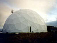
In addition to radome design and fabrication, AFC also offers a complete turn-key system capability. This includes complete installation, performance verification, support equipment, and extended term maintenance. The only aspects not covered by AFC are the antenna design and the site selection. These two items are normally dictated by the mission to be performed.Installation Services Throughout the World
 |
 |
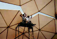 |
AFC maintains an installation team with the experience and capability of installing a radome at any site in the world. Typical services include foundation design and construction, radome assembly, and performance verification. Extended term maintenance contracts are available for any radome, regardless of the manufacturer. These contracts cover both preventive maintenance and repair. The repair aspect frequently includes fabricating replacement panels or structural members to match the design of another manufacturer.
Support Equipment for Full Operational Status
Support equipment typically includes ac power distribution, interior lighting, heating/air conditioning, aircraft warning lights, lightning protection, and interior support for hoists and other mechanical devices. AFC will provide and install all required support equipment to insure that the system achieves full operational status within a minimum time frame. AFC also maintains an inventory of standard support equipment to insure a fast response to any failure.Advantages of Selecting AFC as Your Radome Source
Most radomes must be individually designed and fabricated to satisfy a unique set of requirements. Accomplishing this in a timely manner requires practical experience, engineering talent, effective administration, and a willingness to commit all of these resources to the task.Experience of Over 30 Years
In 1979 Microdyne acquired Antennas For Communications (AFC), an antenna manufacturing company started in 1972. This acquisition enabled Microdyne to offer complete systems for both uplink and downlink satellite communications. In June 1991, AFC was purchased by an employee group.Capabilities to Match Your Fast Response Requirements
AFC has the engineering, manufacturing, and administrative capabilities to respond to your requirements. For example, AFC recently signed a "quick reaction" contract to design and fabricate two, 41 foot dielectric space frame radomes for the US Army INSCOM project. The radomes were completed and ready for shipment 60 days after receipt of the order. An additional three weeks was required for installation and full performance verification. This example is typical of AFC willingness to commit their resources to meeting your requirements.Quality to Last
AFC maintains FAA-STD-016A and MIL-I-45208A Quality Program Requirements. Custom-tailored to insure compliance....fabrication process controls and program tests, record and data audits....at each and every step in radome implementation. This assures top quality, in all aspects, of the final product.Related Standard and Specialized Products
Antennas for Communications offers specialized products to provide superior performance in a variety of applications. These products include antennas, shelters, and waveguide components.Standard and Customized Antennas
AFC's standard antenna line includes conical horn and dish antennas from one to seven meters in diameter. These antennas are currently in use throughout the world for a wide variety of commercial and government customers. The primary applications include microwave links, Television Receive Only (TVRO) downlinks, and satellite uplinks.
AFC also maintains a complete design and fabrication capability to provide custom antennas for specialized applications. Since this capability is an integral part of the company, AFC is able to provide a fast response for customized antennas at a competitive price.
Turnkey Shelters for Specialized Applications
Typical examples of turnkey AFC shelters are transportable up-links and "quick reaction" secure airborne deliverable shelter modules. The uplinks, used by most major television stations, consist of the truck, the transmitting antenna, and the shelter equipped with all necessary electronics. Secure shelters are customized to meet customer objectives and shipping dates and are often configured with environmental controls, appropriate electrical filtering, electronic racks, power distribution, back-up power system and antennas. AFC engineers, along with customer personnel, team to evaluate shelter electronics subsystems where classification permits. Fixed station uplinks are also available for video, audio, voice and data.Custom Waveguide Components and Low Loss Transmission Lines
Custom waveguide components include multi-band feeds, rotary joints, filters, diplexers, OMTs, rectangular to circular converters, special bends and twists, and other custom hardware. Applications serve ground based, airborne and spacecraft environments.The Tallguide® product line consists of a series of oversized waveguides, mode suppressors and transitions which provide exceptionally low transmission losses in comparison to standard waveguide. The attenuation per 100 feet is typically one-tenth of conventional waveguides. This increased efficiency can result in a significant reduction in system costs. The product line includes all necessary hardware for operation in the 5 to 100 GHz frequency range.
AFC manufactures, markets and sells worldwide satellite dish antennas, conical horn antennas, radomes, antenna feeds, microwave and waveguide components, ultra low loss waveguide transmission line TallGuide ®, and shelters. Our customers serve the broadcast, communications, radar, weather and cable industry, defense, government, and government agencies worldwide.
A complete Internet WWW AFC document index may be found in Antennas for Communications (AFC) Home Page Document Summary List.
Table of Contents Top of PageReturn to Radome Network Home Page
Telephone (352)687-4121 Fax (352)687-1203 E-mail sales@afcsat.com
Tallguide is a Registered Trademark of Antennas for Communications
Copyright © 1996 - 2000 Antennas for Communications